
Solar arrays for the Spacecrafts


Introduction
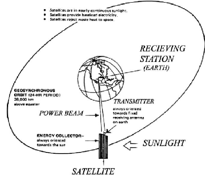
The concept of using solar energy directly from space and then beaming this energy to Earth was first introduced in the late 1960s. The main advantage of placing solar cells in space is that they can utilize 99% of solar energy for 24 hours a day. In this article, solar satellites are used for the collection of solar energy and to transmit this energy, a Wireless power transmission (WPT) system is used. Besides, the Rectenna which is nothing, but the Rectifying Antenna is used to collect the microwave signal. Also, space-based solar power is the need of the hour because fossil fuels are on the verge of depletion. The benefits of this system are that it is environmentally friendly, negligible amount of loss, and is the modern method of energy transfer. A recent survey has revealed that the current consumption rate of oil will result in drying up in the next 65 years. This crisis needs an alternative energy source for future consumption and solar energy is one of the best solutions. At present, we use solar panels to absorb sunlight as an energy source to generate electricity. On the other hand, there are two major disadvantages of using solar energy on Earth. Firstly, sunlight is not available at night and secondly, sunlight sometimes gets obstructions due to clouds. The solution to these difficulties is to install solar panels in the space itself with the help of satellites. Hence, Solar Power Satellites (SPS) are a crucial part of Space Based Solar Power (SBSP).
Solar power satellite
To start with, the space system itself can be divided into two major parts. The first one is the satellites, which are usually earth-orbiting objects. Due to this, the satellite receives nearly constant solar irradiation. The main purpose of the satellite is to give a bird’s eye view of the earth’s large portion for the collection of data from various land and ocean areas. besides, the other purpose is to transfer data for communication links. Additionally, to achieve maximum working efficiency, most of the satellites rotate in the Low Earth Orbit (LEO) [180-2000km above the earth’s surface]. The second major part is the spacecraft, these are usually used for deep space probe missions and interplanetary explorations. But for now, let’s just concentrate on the earth orbiting solar satellites.
1] Solar array location:
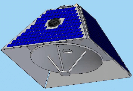
a) Body-mounted arrays: These arrays are directly mounted on the body of the satellite. This type of mounting is mostly used for small-sized satellites such as CubeSat, SmallSat, etc. due to space constraints. Also, the solar panels can be efficiently packaged along with the payload of the system.
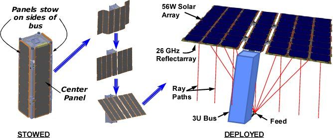
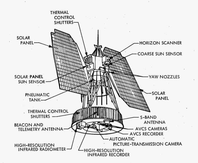
b) Deployed arrays: This type of mounting is mostly used for large-sized satellites with high power requirements. In this type, the solar cells are mounted on wings which are deployed once the spacecraft reaches its defined mission orbit. The arrays should be flexible as the wings must also be stowed during launch and this stowed volume influences the size and design of the wings. On the other hand, for low-altitude orbits, the atmospheric drag can be a major factor and this increases as the area of the wing increases. also, large wings will increase the overall mission cost and launch cost. But the solar satellites require large solar array wings to generate a high amount of power, hence to overcome this problem solar satellites mostly use Geosynchronous orbit (GEO) [36000 km above the earth's surface] as there is no atmospheric drag present.
2] Space solar array construction:
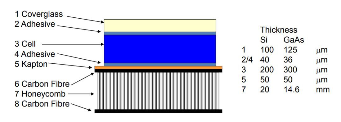
a) Cover glass: Solar cells are fitted with cover glass to reduce the optical reflection and the damage done by radiation in space and to improve the surface thermal emittance. Two materials are almost exclusively used in current technology: Corning 7940 fused silica, and Corning 0211 micro sheet glass. The fused silica is more resistant to darkening by ultraviolet and electron radiation; this may be a significant factor in regions where thick cover glass is required. Micro sheet, on the other hand, is less costly, and small. Adequate for use in regions where a relatively thin shield can provide insulation. The electrical efficiency of solar cells is enhanced by a thermal design of the array which provides the coolest possible operating temperature for the cells. Materials and combinations of materials are used which minimize the ratio of solar absorptivity to blackbody emissivity. Hence, both the front and rear surfaces of the array should be covered with cover glass for temperature optimization.
b) Adhesive: Adhesives are used to connect the solar cell to the substrate, and the glass cover to the surface. The types of adhesives that are usually used are silicones and epoxies. The adhesives are applied uniformly in thicknesses ranging from 0.025 to 0.050 mm. The adhesives based on epoxy are often adjusted by adding a plasticizer to provide stability at low-temperature rates. On the other hand, silicones are stable over a wide range of temperatures.
c) Honeycomb: Honeycomb panels are advanced sandwich elements that consist of low-module lightweight cellular (honeycomb) core sandwiched between high-module, high-resistance face sheets. The assembly maximizes the ratio of rigidity to weight and the ratio of bending strength to weight, resulting in a panel structure that is especially effective in carrying both in and out of plane loads.
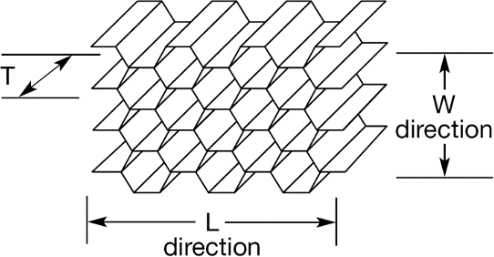
The selection of the center of the honeycomb plays a major role in determining a panel’s structural efficiency. In addition to preserving a distinction between the two face sheets and thus strengthening the panel’s bending rigidity, the honeycomb core often plays the role of carrying out-of-plane shear stresses. The Honeycomb cores are typically generated through the cycle of expansion. During this procedure ribbon foil stacks are bonded along regularly spaced lines to form a solid, unexpanded block. Afterward, the stack can be expanded to form a hexagonal core. The procedure results in walls of double thickness along the direction of the ribbon (known as direction L). The direction of expansion is termed the direction of W. The honeycomb cores have superior shear strength in the L direction because of the double-thickness walls. The cell walls are perforated for spacecraft applications to allow for venting during ascent.
d) Kapton: It is a polyimide film that remains stable across a wide range of temperatures from −269 to +400C. It is mainly used in the satellite for thermal insulation purposes.
3] Difference between Terrestrial solar panels and Space solar panels
- Their weight is improved.
- They are designed to be space radiation resistant.
- The components don’t need to insulate them against corrosion as there is no moisture present in the space.
- They do not require any mechanical support, as it is necessary for use in terrestrial solar panels
4] Earth satellite orbit types
There are 2 orbit choices to fixate the satellite into space:
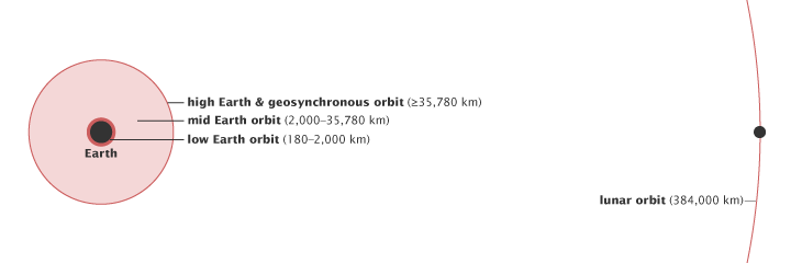
a) Low Earth Orbit (LEO): It is normally at altitudes between 180 and 2000 km. The satellite’s speed of travel is about 8 km/s. Besides, the approximate orbit duration is about 90 minutes (depending on altitude). This orbit is mostly used for remote sensing, military purposes, and manned space flights (except for interplanetary missions). The rapid orbit time allows repeated observation of the same area of the Earth’s surface although the satellite does not stay in the same relative position throughout the path of the satellite processes across the Earth’s surface with successive passes. for example, the International Space Station is in low Earth orbit.
b) Geosynchronous Orbit (GEO): Its orbit duration is of 1 day but has an elliptical orbit with an inclination to the equatorial plane. The Geostationary orbit is a particular case of the Geosynchronous orbit but the terms are often used interchangeably and the acronym is usually the same (GEO). It circles the Equator from west to east at a height of almost 36000 km. The orbit is circular with an inclination of 0 degrees to the plane of the equator. In addition to that, orbit duration is 23 hours, 56 minutes, and 4 seconds – i.e. the length of one day. Therefore, the satellite appears to be “stationary” over a location on Earth. This orbit is mainly used for communications satellites, three equally space satellites can provide full coverage except for the polar regions at a speed of travel of about 3 km/s. Also, as mentioned earlier in the above section, to avoid atmospheric and gravitational drag, the solar satellite will also rotate in the geosynchronous orbit.
Factors affecting space solar array
1] Temperature: The temperature of any entire spacecraft is regulated entirely by radiation since there is no convection or conduction medium. Optimizing radiation from the array is necessary to keep the PV array cool. Avoid absorption of excessive energy, often using “tuned” cover glasses on the cells to resist the IR and UV irradiation the cells are unable to use. Maximize heat flow away from the array using surfaces with high emissivity to radiate heat to deep space. There will be significant temperature differences between full sunlight at the front of the array and darkness at the rear. In sunlight, operating temperatures typically vary between 30 and 90C in the eclipse, the temperature of the array may range from -10C for a LEO-mounted body panel to -140C (worst case for a deep eclipse of the deployed GEO array).
2] Van Allen radiation belt:
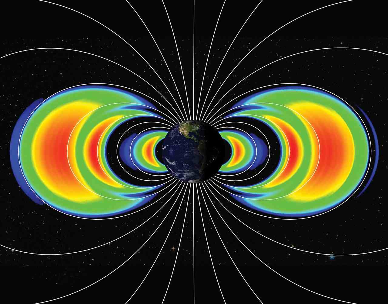
In this, the protons, electrons, and heavier ions are “caught up” by the magnetic field of Earth in “belts” named after the discoverer “Van Allen”. Electron energies range from a few keV to around 7 MeV. While the protons and ions energies range from a few keV to around 500 MeV. A small number of particles have higher energies than these values but from a spacecraft design point of view, they are not important. The spatial distribution varies according to several orders of magnitude with altitude and orbit inclination. Besides, the South Atlantic anomaly – the 11C disparity between the magnetic and spatial poles and the offset of the Earth’s spatial and geomagnetic centers creates a magnetic disturbance over the South Atlantic and charged particles are trapped at lower altitudes here (about 400 km). Therefore, Van Allen belts are a problem for any orbit because the spacecraft must travel through them.
3] Atomic oxygen: At altitudes of 200-700 km, atomic oxygen is the major constituent of the atmosphere (109 atoms cm-3 at Shuttle orbital heights of 250 km, 107 atoms cm-3 at International Space Station orbit of 500 km). Atomic oxygen is very reactive and erodes material, especially exposed silver on interconnects. It can lead to an array of failures and is a factor in the determination of mission lifetime. The array should have all vulnerable surfaces protected (e.g. with the combination of cover glass and adhesive). Also, the erosion of surfaces can lead to thermal, electrical, and optical changes, altering the operating environment of the solar array.
4] Micrometeoroids and debris: Micrometeoroids are the remnants of comet orbits and exposure is increased whenever the Earth’s orbit intersects with that of a comet. The orbital debris includes spent rocket stages and fragments of rockets and spacecraft. There are at least 19,000 known man-made objects of at least 10 cm in size in LEO and GEO and probably hundreds of thousands of smaller items. They cause damage from collision and can increase other operational problems (e.g. atomic oxygen interactions, array charging). Also, impacts can change the thermal, electrical, or optical properties of the array. the arrays are designed with redundant contacts to allow for damage to parts of cells without taking out the whole string. Besides, the risk of damage is increased for long mission duration, increased spacecraft size, and certain altitudes and orbits. The large solar wings are particularly vulnerable.
5] Magnetic moment control:
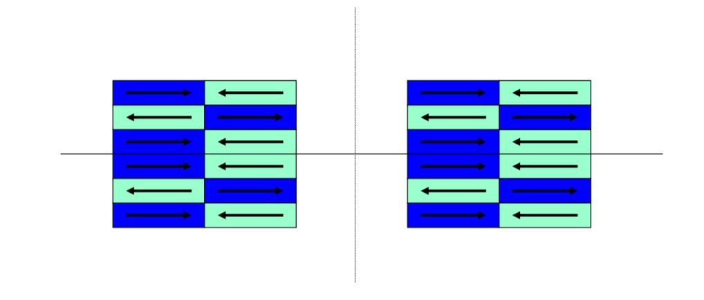
The movement of the electrical currents in the array in the presence of a magnetic field leads to torque on the array. To eliminate this phenomenon, the array should be designed for magnetic field cancellation by using a mirror configuration for the strings.
Advantages and Disadvantages
1] Advantages:
- Full solar irradiation would be available would be always which results in about 5 times the solar energy as compared to the best terrestrial sites on Earth.
- The antenna could be directed at any Rectenna located on the Earth.
- The zero gravity and high vacuum conditions in space would allow much lighter, low-maintenance structures and collectors.
- No fuel is required.
2] Disadvantages:
- The entire structure is Humongous.
- High cost and requires a huge amount of time for construction.
- The risk involved with malfunction.
- High power microwave source and high gain antenna can be used to deliver a burst of energy to a target and thus can be used as a weapon.
Conclusion
In conclusion, Space-based solar power is the futuristic alternative to conventional terrestrial solar energy. Additionally, the solar satellite is one of the most important parts of the SBSP concept, and to get solar irradiation from the sun intensively, the satellite should be improved concerning design considerations. Even though the concept is very expensive, and it will take time for construction on the brighter side, it will provide a power supply 5 times that of best terrestrial solar panels 99% of the time of the year.