
The Repair and Diagnosis of PV Modules

Introduction
If you’ve installed the right Solar PV system configuration, then you’ll enjoy the comfort of having smooth power at home. But there are many transitions, conversions and distances it travels before it reaches the electrical appliances. Before giving final output, the solar energy experiences many conversions and the losses in your solar power system. Although the panel’s solar power is much more than the energy that we receive as an output for running the electrical appliances. Most of the energy in the solar power system either gets lost as the loss of conversion within the components or as a loss of transfer through wires.
Wire malfunction and Losses
The energy we receive as the output which runs our electrical appliances needs a medium to travel from one point to the other and this medium is supplied by wires. The various solar energy system components are connected via copper wires. When the energy travels through a wire some of it gets lost to the surroundings as heat. The longer the distance between the solar panel and your electrical appliance, the more energy wastage as heat becomes. Therefore, one should try to maintain minimum or optimum distance and proper wiring sizing between the different components and the electrical load. DC wiring losses are mainly caused by the cabling’s ohmic resistance that interconnects PV devices and strings, although the connections and fuses may also result in losses. Thepower loss will vary as a function of the squared array current. Differences in cable length or size between parallel strings may result in differences in voltage drop, thus contributing to mismatch. Another source of voltage drop is series protective diodes.
Mismatch effect in Modules and Arrays
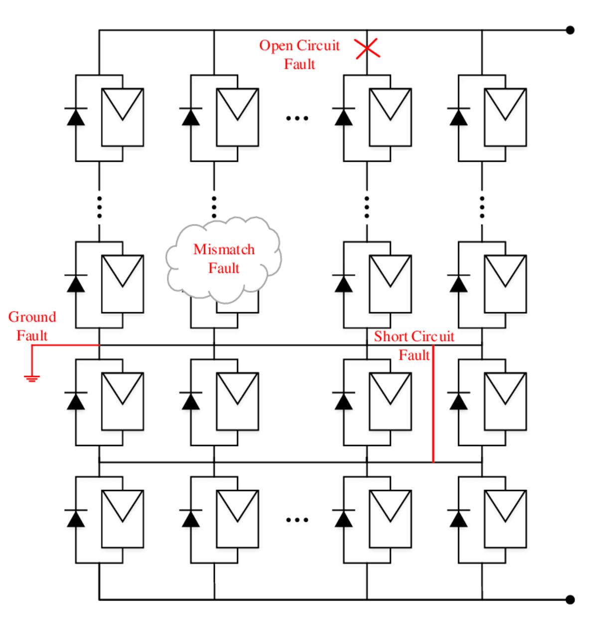
Losses of mismatch are caused by interconnecting solar cells or modules that do not have identical properties or that encounter different conditions from each other. Mismatch losses are a serious problem in PV modules and arrays under certain conditions, because the solar cell with the lowest output determines the output of the entire PV module under worst-case conditions. For example, if one solar cell is shaded while the rest is not in the module, the power generated by the excellent solar cells may be dissipated by the lower performance cell instead of powering the load. This in turn can lead to highly localised power dissipation and the resulting local heating can cause irreversible damage to the module. Mismatch in PV modules occurs when one solar cell’s electrical parameters are significantly altered from the rest of the devices. The impact and loss of power due to malfunction depends on the PV Module Operating Point, circuit settings and parameters (or specifications) which differ from the rest of the solar cells. Differences in any part of the IV curve between one solar cell and another may lead to losses inappropriate at some point of operation. Although there may be inconsistencies in any of the cell parameters shown below, large inconsistencies are most commonly caused by differences in either short-circuit or open-circuit voltage. The impact of the malfunction depends on both the configuration of the circuit and the type of mismatch.
Since most PV modules are connected in series, the most common type of mismatch encountered is series mismatches. A mismatch in the short-circuit current is more common among the two simplest types of mismatch considered to be the mismatch in short-circuit current and open-circuit voltage as it can easily be caused by shading part of the module. Also, this type of malfunction is the most severe.
A mismatch of series-connected cells in the open-circuit voltage is a harmless form of mismatch. As shown in the animation below, the overall current from the PV module is unaffected at short-circuit current. The overall power is reduced at the maximum power point, because the poor cell generates less power. Since the two cells are connected in series, the current is the same through the two solar cells, and the overall voltage is found by adding the two voltages at a given current.
Depending on the module’s operating point and the degree of mismatch, a mismatch in the short-circuit current of series connected solar cells can have a drastic effect on the PV module. As shown in the animation below, the impact of a reduced short-circuit current at open-circuit voltage is relatively minor. Owing to the logarithmic dependence of open-circuit voltage on short-circuit current there is a minor change in the open-circuit voltage. But since the current must be the same through the two cells, the overall current from the combination cannot exceed that of the poor cell. Thus, the current from the combination cannot exceed the poor cells short-circuit current.
The extra current-generating capacity of the good cells is not dissipated in each individual cell at low voltages where this condition is likely to occur as would normally occur in the short circuit but dissipated in the poor cell instead. Overall, severe power reductions are experienced in a series connected configuration with current mismatch if the poor cell produces less current than the maximum power current of the good cells and if the combination is operated at short or low voltages, the high-power dissipation in the poor cell can cause irreversible damage to the module.
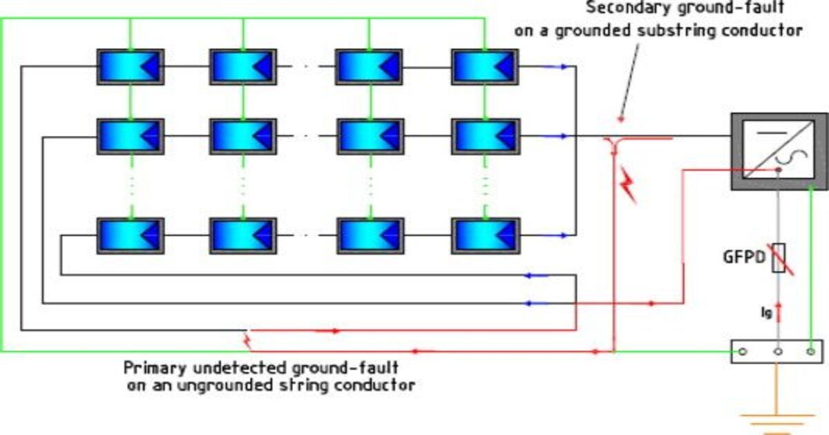
DC Earthing fault
The most common type of fault in PV systems is DC ground faults, and half go undetected. A DC ground fault is the unwanted condition of the current flowing through the grounding conductor of the equipment in the circuits carrying DC power before the inverter. Ground faults can cause significant safety issues, such as arc faults and arc flashes in the case of high voltage. In addition to a safety hazard, ground faults create fire hazard because short-circuited current heats bare metal. Let’s review some terminology to better understand a DC ground fault and look inside a PV system.

The term grounding, as defined by the National Electrical Code, is:
- Grounding Equipment Conductor (EGC) = The conductive path(s) that provides a ground-fault current path and normally connects non-current metal parts of the equipment together with the grounded conductor or the grounding electrode conductor of the system.
- Grounding Electrode Conductor (GEC) = A conductor used to connect the grounded conductor of the system or equipment to a grounding electrode or to a grounding electrode point.
- Grounded Conductor = A deliberately grounded system or circuit leader.
The EGC serves to bond all conductive parts (modules, racking) together and provide a path to the GEC. The GEC connects the grounding electrode to the EGC, and thus the entire system. The grounding electrode is a large metal rod that is driven at least 8 feet deep into the earth. Usually it’s copper, aluminium, or aluminium clad in copper. Current flows through the EGC or any piece of metal that is grounded due to unintended contact with the grounded conductor in a DC ground fault. This contact typically occurs because of damaged insulation of the conductor, improper installation, pinched wires, and water, which can create an electrical connexion between the conductor and the EGC.
1] Diagnostic techniques: As already mentioned, it is difficult to detect a DC ground fault, especially in large PV systems. This is because defects in DC ground are often less than the GFP device’s minimum sensitivity. Insulation resistance monitoring and residual current detectors (RCDs) include techniques for the detection of DC ground faults. To measure grounding resistance, it is advisable to carry out a grounding test every morning using an insulation resistance monitor. This must be done while the array is in open circuit state. The test reveals two possibilities-the resistance to insulation is above the minimum and the system can start or the resistance to insulation is below the minimum. That indicates damaged insulation and the possibility of ground failure. RCDs can also be placed on array conductors to measure anomalous current indicating a ground fault. Even if the ground defect detection interrupter (GFDI) in the inverter trips the circuit successfully it can be difficult to locate the source of a ground defect. First, technicians should check whether a continuity test is blown into the GFDI. A continuity test is performed by placing a multi-meter leads at a fuse ‘s metal ends and turning the dial to resistance. If the resistance is high the fuse will be blown and will have to be replaced. Next, technicians should use an insulation tester to perform an insulation-resistance test on the conductors.
In practise, identifying the source of a ground fault may be challenging, as a ground fault can occur at any point in the circuit between the grounded conductor and the EGC or a metallic component. To determine the source of a fault on the ground:
- Ensure the inverter is isolated by removing the positive and negative conductors from the array.
- Close the DC disconnect to put the conductors at a live voltage.
- Measure the voltage between the positive and negative conducers to determine the array’s open circuit voltage.
- Measure positive to ground, and ground negative.
Hot spots heating effect
A cell ‘s output declines when shaded by a branch of a tree, building, dust module or any other factor. The output is decreasing in proportion to the amount of shading. For completely opaque objects like a leaf, the decrease of the cell’s current output is proportional to the amount of the cell that is obscured. Hot-spot heating occurs when there is one low-current solar cell in a string of at least several high-current solar cells because of shading.
Hot-spot heating occurs when a large number of connected cells in series causes a large reverse bias across the shaded cell, resulting in large power dissipation in the poor cell. In the poor cell, the entire generating capacity of all the good cells is essentially dissipated. The enormous dissipation of power that occurs in a small area results in local overheating, or “hot-spot,” which in turn leads to destructive effects such as cell or glass cracking, solder melting or solar cell degradation. The causes are stated below:
- Shading: overhead objects (e.g. trees, poles, etc.), overgrowth of vegetation, surface fouling, surface foreign objects.
- Mechanical damage: broken glass, broken/bent frame, collisions between modules or other objects, improper mounting
- Internal module failures: cell material defects (ex. shunts, high series resistance, etc.), cell cracks, local de-lamination, poor solder joints
- During the design phase of the system the effects of shading and soiling can be mitigated. A detailed study can be carried out to determine the effects of trees, poles, or other objects that can shade the modules all day and year-round. With the periodic maintenance of the system, soiling can be mitigated.in conclusion, it can be said that hot-spot can have a serious effect on plant life and performance. But, it can be avoided through a robust O&M practices.
Battery issues
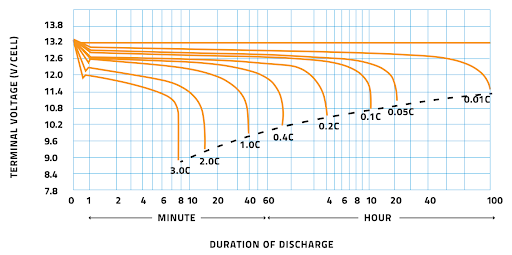
It is almost impossible to estimate how long a given battery will last, since there are many factors influencing a battery’s life cycle. These include the type of battery, the number of cycles of charging / recharging, operating conditions such as temperature, how fully the battery was discharged among others. If all battery systems are managed properly, a battery will die after all active materials have been consumed or the positive grids have deteriorated due to corrosion that occurs throughout the lifetime of the battery. Failure to follow appropriate design guidelines and system management will almost always guarantee early failure of a battery system. Eight ways to kill a battery:
- Overcharge
- Over discharge
- Excessive charge rates
- Excessive discharge rates
- Improper equalization
- Too hot or cold operational environment
- Extended storage period
- Improper battery for a given application
During the day, solar energy is available, but energy is also required during the night. This makes batteries a very important part of the solar energy system, since they can provide constant electrical power whether the source of energy is available. Owners of solar energy systems need a reliable long-lived battery – not to mention an affordable price. It can be difficult to find a battery that meets all these requirements. Due to the many charging/discharge cycles that occur during the day and night, batteries in solar energy systems require a long service life. Because the battery must have power appliances during the overnight hours, it should also have a high capacity and be able to operate without damage when deeply discharged – this is known as deep-cycle storage capability.
Conclusion
In conclusion, this article focuses on a state-of-the-art literature review was introduced, which observed types of faults in different PV modules and highlighted the benefits and disadvantages. Disadvantages with different condition monitoring and fault diagnosis techniques were observed with respect to different output characteristics and performance parameters of the PV modules. Thus, the focus is developed on the diagnostic techniques, which can extract distinguished features that could distinguish between different types of fault.