
An Introduction to Photovoltaic Modules

Introduction to Solar PV Modules
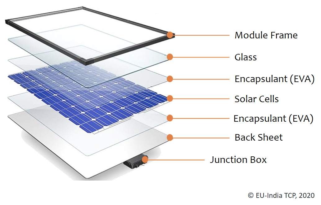
To understand the basics of photovoltaics, we must first come to the building block of solar panels which are known as solar cells and their types, interconnections and ratings as per industry standards. In photovoltaics, many cells combine to form a solar panel and many panels combine to form an array.
Typically, residential systems use panels made from 60 solar cells whereas commercial systems use panels made from 72 solar cells. As we increase the number of cells, the voltage and power generated also increases. They’re insulated and framed to be protected from harsh environmental conditions and also to protect the user from untoward accidents. So, in this article, you’ll be able to obtain a basic understanding of solar photovoltaics, types and important factors that need to be considered when investing in solar technology.
Series and Parallel Connections in Solar Modules
The basic ‘nerves’ of the solar module array which sends signals or currents to different parts of the system principally depends on the module circuits are designed in such a way that the multiple cells that make a module are connected to increase the power and voltage obtained from the device. The design is done under standard test conditions where maximum power is acquired at 0.5V at 25°C. Therefore, when it comes to circuit design of PV modules, there are 2 classifications which are:
- Modules connected in series
- Modules connected in parallel.
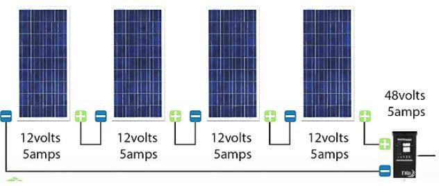
Modules connected in series usually consist of wiring the positive terminal of one solar cell to the negative terminal of another solar cell such that voltage increases and current remain the same across the circuit.
However, since wiring is involved, there’s a chance for mismatch losses to occur. These losses are caused by interconnection defects of solar cells or solar modules because of varying properties or conditions. For example, if a part of a solar cell or module is shaded, the overall power being generated will be lower than the expected system performance output because the power that’s being generated at the good side of the cell/module will be dissipated due to improper wiring. This, in turn, will lead to localized heating which may damage the cell or module irreversibly. Most of the PV modules are connected in series which leads to a higher chance of series wiring mismatch that occurs in the circuit. There are 2 types of series mismatches:
Open-circuit voltage mismatch: This is a mismatch that’s not significantly threatening to the module but its effects are pronounced when the overall power is being calculated. In series, current remains the same but the overall voltage is increased by adding voltages at various values of current.
Short-circuit current mismatch: A short circuit current mismatch has a drastic effect on the module because current passing through the solar cells is the same. The overall current depends on the ‘poor cell’ because it cannot exceed it. This leads to dissipation of power at the poor cell which can cause perpetual damage to the module
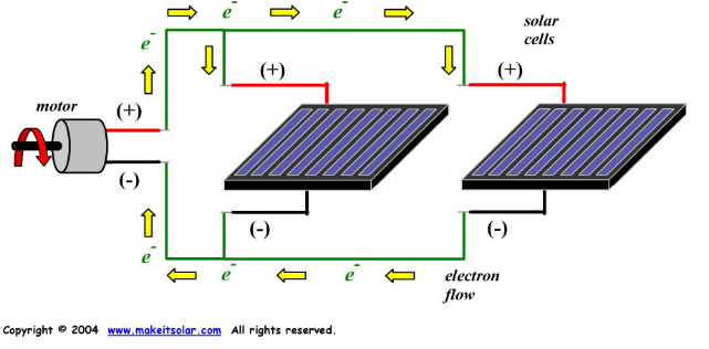
Modules connected in parallel involve connecting all the positive terminals together and all the negative terminals together in the module. This wiring increases the current flowing through the circuit and keeps the voltage same throughout.
Mismatch Effects in Solar Modules
Usually, in PV systems, we find a combination of series and parallel wiring. This is common in large systems used for residential or commercial purposes. The combination wiring is used for large PV arrays wherein a set of solar cells/modules connected in series is known as a ‘string’. Since a combination wiring design is used, there are chances for mismatch effects to occur at an array scale because of the series and parallel connections present in the circuit design.
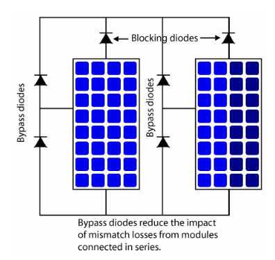
These effects can significantly affect the entire array if by-pass diodes are not connected. By-pass diodes are connected in parallel. They help in reducing the effective resistance and are usually accompanied by another diode called a ‘blocking diode’ which prevents overloading in the module. They are wired in series.
Each string present in the array should be equipped with its own blocking diode because these diodes reduce mismatch losses that frequent in arrays having parallel connections by inhibiting the flow of current from parallel strings to strings of lower current. They prevent current from flowing into modules that are possibly shaded which if it did flow, can lead to overheating and solar cell damage
Fortunately, with current developments in loss management and encapsulation techniques, manufacturers can give a module lifetime guarantee for more than 20 years where for the first 10 years, the module will produce 90% of its total rated output and approximately 80% for the next 25 years which shows the robust nature of PV modules in the current market.
Market Trend of Solar PV Modules
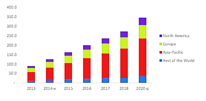
When we consider the current market for solar PV technologies, there is an expected to grow to USD 345 billion by 2020. The main reasons for this projected growth are because of increasing demand for energy, a noticeable concern for sustainable practices and the Government’s support for the same.
Solar panels made from crystalline silicon are expected to hold the majority of the market share because of their semiconductor properties and competitive costs in the market. Photovoltaic technology made from inorganic materials such as Silicon, CdTe, CIGS, Amorphous silicon, etc. are the major contenders because of their potential to achieve high efficiencies. The utility applications have the highest demand for PV market primarily in defence, space utility, military applications and in power plants.
The Asia-Pacific (APAC) region had the largest share in the PV market because of Governmental initiatives to shift towards the Renewability sector. Therefore, the production costs are low and often supported by Government subsidies. The major contributors from these regions are India, South Korea, Japan, China and Thailand
Types of Solar Panels
Since the market trend is expected to play a major role in solar panel production, it is essential to know the different types of panels that exist in the market.
There are mainly 5 types of solar panels that currently hold the market. They differ in terms of manufacturing processes, properties, cost and efficiencies and the panel type must be selected according to the installation type that is being considered. They are known as:
- Monocrystalline solar panels
- Polycrystalline solar panels
- Multi-junction solar panels
- Thin-film solar cells
- Bifacial Panels
- PERC Technology
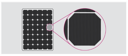
- Monocrystalline panels: These are made from silicon wafers which are cut from pure silicon ingots. These panels look like black cells because of how light interacts with pure silicon crystals. These monocrystalline wafers are cut at the edges to give an octagonal shaped wafer. They have high efficiency and performance with an efficiency of around 20%. These panel types generate the highest wattage with values in the range of 300-400W.
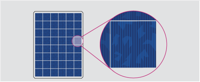
- Polycrystalline Silicon Panels: These solar panels are made from fragments of silicon crystals that are melted together to form wafers. These have higher defects because of the use of different silicon crystals that are moulded together. Hence their efficiency values are in the range of 15%-17% with significantly lower wattage values than monocrystalline solar panels. However, they are economical when it comes to cost. Polycrystalline solar cells have a bluish shade to them because of the light that’s being reflected off from different fragments of silicon.
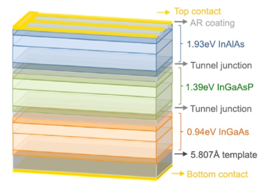
- Multi-Junction Solar Panels: The major loss in solar cells is the incapability of a solar cell to harness all the light energy from the sun and thereby leading to power losses. There are 2 reasons why this takes place: Firstly, if the photon energy is lower than the bandgap energy, the energy from photons is not collected at all. Secondly, if the photon energy is larger than the bandgap energy, the excess energy leads to the formation of heat which causes more heat losses in the solar cell known as ‘relaxation’. Therefore, a new type of solar cell called multi-junction solar cell which comprise of multiple layers each having different bandgap values. This means that light consisting multiple wavelengths can be extracted by multi-junction solar cells because each layer will correspond to different wavelengths of light thereby minimizing losses. These cells consist of layering the material with the biggest bandgap on top because materials with big bandgaps have short wavelengths. So, light of short wavelength can be effectively absorbed by the top layer. Materials with short bandgap and large wavelengths are placed at the bottom or layered below the top material so that the light of longer wavelengths can be extracted before it transmits through the cell. Since there are many layers being utilized, transparent conductors are used to collect generated electrons at each layer. There are tunnel junctions between each sub-cell to lower electrical resistance and to increase electron flow. They are highly doped, large bandgap diode which reduces the depletion region to allow transfer of charge effectively
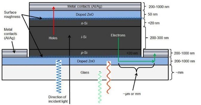
- Thin-film Solar Panels: As the name suggests, are manufactured around 350 times slimmer than crystalline wafers used for monocrystalline and polycrystalline solar cells. They can exhibit both black and blue shades in colour depending on the material they’re made from. They’re usually made from materials such as Cadmium Telluride (CdTe), Copper Indium Gallium Selenide (CIGS) and even amorphous Silicon which is not made from conventional solid silicon wafers but are instead made from non-crystalline silicon. Materials such as CdTe and CIGS are placed as a layer between transparent conducting layers to absorb sunlight for photovoltaic conversion processes. The main advantages of thin-film technologies are its lightweight nature, portability and flexibility which enable these cells to be adaptable to any surface. They’re also aesthetic which helps in customer retention towards renewable technologies. However, their major disadvantage is its low efficiency with a value of around 11% which are subject to increase with research and development. Also, unlike monocrystalline and polycrystalline solar cells which come in standard sizes of 60, 72 and 96 cells, thin-film solar cells don’t have uniform sizes and the output power depends on the physical size pitched for that particular application

Amorphous Silicon Panels: Another commonly used thin-film technology is amorphous silicon which has been one of the most widely used thin-film technologies in the market ranging from powering remote facilities to even pocket calculators. This technology involves depositing a thin silicon layer on a substrate such as metal or glass which is layered in a p-i-n structure. Their major advantages are its sensitivity to light which aids in light absorption, heat resistance and flexibility which makes them less prone to panel breakage during its installation and transport. It can be manufactured in a variety of shapes and sizes and have low manufacturing costs making the technology more accessible. On the other hand, this technology has lower lifetimes than of monocrystalline or polycrystalline solar cells and its efficiency is only around 7%-9% because of an effect called as the Staebler-Wronski effect which degrades the performance of the panel during its initial exposure to sunlight leading to a decrease in the efficiency from around 10% to 7%
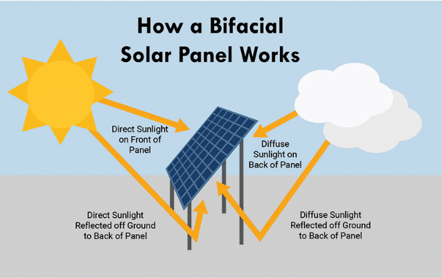
- Bifacial Panels: A different type of solar technology called bifacial solar panels has been developed. Bifacial solar panels are those panels which are able to generate power from both sides of the panel. These panels are installed on surfaces that are highly reflective. These panels help in increasing the power generation by 30%. They are also durable, have minimized potential-induced degradation and are UV resistant. They operate by making use of the light reflected off the ground called as albedo light using solar cells designed at the bottom. They mostly use monocrystalline panels although in some cases, polycrystalline panels are also used. They were found to increase efficiency by 11% and even more if sun-tracking systems are used .
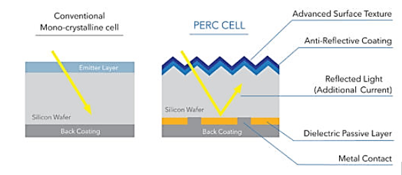
- PERC Technology: As solar technology and panels are constantly evolving to be more efficient, a new type of technology called PERC solar cells have hit the markets. Perc is an acronym for Passivated Emitter and Rear Cell/Contact. They have found to improve the efficiency of a solar cell by introducing a passivating layer at the back surface to improve rear contact light absorption and charge generation. This gives the cell another chance to absorb the light that would otherwise get transmitted through the cell. It also reduces recombination effects and absorption of heat. PERC cells reflect light of wavelength higher than 1180nm. In a conventional solar cell, light of this wavelength would have been absorbed and would have led to the cell absorbing heat which would hinder optimum efficiency. PERC technology has only 2 additional manufacturing steps which don’t affect the cost significantly. In the end, a solar cell of higher quality and durability is obtained. The 2 steps are:
- Addition of passivating layer at the back surface;
- Opening of small pockets in the passivation layer by chemical/laser etching.
These steps are done to ensure the benefits offered by PERC technology are established during its operation
Module Ratings
When considering solar panel and its installation, it is necessary to know the module ratings for the panel because that will determine the efficiency of rated output power generated from the panel. Some factors to consider are:
- Wattage: Generally, solar panels have wattage values between 250 to 400 watts under ideal conditions. Higher the wattage, higher is the efficiency. Having high wattage also enables the use of lesser modules to achieve the required output. Wattage is measured by multiplying the total current and voltage generated from the solar panel.
- Peak Sun Hours (PSH): This is the equivalent number of hours where the total solar irradiance is equal to 1000W/m2. This is important in calculating the total output energy the solar panel will produce for one particular location. The PSH will vary according to the geographic location.
- Efficiency Ratings: Efficiency ratings indicate the quality of the panel and when opting for installation, an average efficiency value of around 18%-22% should be taken into consideration.
- Range of Ambient Temperature: Typically, solar cells have a temperature range between -20oC to +85oC. If panels operate above or lower than this temperature range, there will be a decrease in the rated output. Therefore, solar panels are often equipped with optimizers and inverters which constantly regulate the panels in extreme conditions
Module Sizing
Apart from these factors, it is also necessary to consider the system sizing of the solar cells and arrays because it can significantly affect the energy yield as well as the cost of the investment into this technology.
The first thing that needs to be measured is the total kilowatt-hour use for the past 1 year. The peak sun hours for the proposed site must also be taken into consideration. Then to determine the system size, the following equation must be taken into consideration:
System size=Annual kWh x Annual PSH x Derate factor
Derate factor is the value of the unavoidable losses that a system encounters when converting the array’s DC into AC.
To size a string, we must do the following:
- Find the temperature difference with the ambient (ΔT)
- Multiply ΔT x Temperature coefficient voltage Voc
- Add 1 to determine the increase in voltage and multiply by open-circuit voltage (Voc)
- Then divide the maximum inverter input rating from the output value in step 3
- If the calculations are being done for cold temperatures, round down the final value but if it’s being calculated for hot temperatures, round up the value.
An example would be:
Given: Calculate number of modules that need to be configured in series
- Cold temperature = −14°C
- Temperature Coef Voc= −0.35%/°C
- Voc = 36Voc
- Inverter Max input voltage = 600V
Solution:
- 14+25=39oC
- 39 x -0.35% = 0.1365
- 0.1365+1 = 1.1365
1.1365 x 36 = 40.914
- 600/40.914 = 14.66
Since we’re calculating number of modules in cold temperatures, we should take just 14 modules.
The required wattage of modules can be calculated by:
Module watts needed = System size / Total number of modules
Hence, to size an array, apart from the above equations we need to consider the array length and width, module size and orientation, tilt angle (if required) and hardware requirements which shall be explained in another article
Conclusion
In conclusion, we can see that when it comes to understanding the basics of photovoltaics, there are multiple concepts we need to understand which have been briefly explained in this article. This article gave an overview of the wiring sequences that are most commonly used in solar panel connections followed by the mismatch losses that occur due to the complexity of these wiring practices. This article also followed the current market trends and how it’s expected to grow in the future due to the ever-increasing energy demands and the rise in concerns of sustainability. The different types of solar panels that dominate the world market have also been discussed followed by some factors and parameters that are important during the sizing of such PV systems for utility applications. From this time, it is important to contemplate the current circumstances under which the renewable energy sector is growing and how it is going to impact the future of the energy industry with a positive change!