
The Effect of Heat and Temperature on Photovoltaic Modules

An Introduction to Heat and Photovoltaics
PV modules and cells are meant to convert the light from the sun into electricity. This implies hours and hours of exposure to the sun’s heat for the PV modulessola. The way solar cells are arranged to form a PV module, has a side-effect which physically affects the PV module. The arrangement of PV cells into a module changes the flow of heat into and out of the module. A changed flow of heat means that the temperature at which the module operates increases. This increase in the temperature causes a lowered output voltage for the PV module. This implies a reduced output power. An increase in the temperature also promotes the degradation or failure of a PV module as increased temperatures are linked with thermal expansion. Moreover, increased temperatures also increase the degradation rate. The operating temperature of a PV module is determined using the equilibrium between the heat that the PV module produces, the heat that the PV module loses to the environment, and the ambient operating temperature.
There are different factors that affect how much heat the PV module produces such as the module’s operating point, optical properties, and how densely the cells are packed in the module. The module can lose heat to the environment using one of the three heat transfer mechanisms i.e. conduction, convection and radiation. These mechanisms depend on the thermal resistance of the materials that the module is made up of along with the emissive properties of the module. The conditions, in which the module is mounted in, such as the speed of wind, also determine the mechanisms. This article aims at explaining in depth how heat is generated and lost in PV modules, along with other associated concepts that will help us gain a better understanding of how temperature affects PV modules.
Generation of Heat in PV Modules
The PV modules being used today have an average module efficiency of about 15-20%. This means that on an average, only fifteen to twenty percent of the light that is incident on a PV module is converted into electricity. What about the rest of the light? PV modules generate heat as a by-product. Most of the remaining light (other than that converted into electricity) is turned to heat.
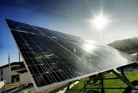
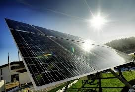
When sunlight becomes incident on PV modules, not all of it is absorbed. As shown in the image above, PV modules have reflective top surfaces that do not let the module absorb the entire light incident on it. The reflected light is not useful as it does not produce any electrical power. And so, any light reflected from the top surface of a cell or module is considered to be a source of power loss. It is thus, necessary to minimize the amount of reflection. In the case of standard PV modules, where the top surface is made up of glass, the light that is reflected off the module consists of approximately 4% of the energy of the incident light. Although, reflected light does not contribute to the heating of the module, it is an important quantity which is used to calculate the maximum temperature rise of a PV module whereby, the incident power is multiplied by the reflection. Where reflection does not contribute to the heating of a module, there are other factors which do. These are discussed below:
- Operating electrical point and efficiency of the module: The operating point refers to the current and voltage output point at which a module is operating. The operating point along with the efficiency of a solar cell/module is the determining factor for the amount of light absorbed which is converted into electricity. At short-circuit current (ISC) or at open-circuit voltage (VOC), a cell or a module is not generating electricity. Thus, all the light that is absorbed at ISC and VOC is converted into heat.
- Light-absorption in parts of the module which are not covered by PV cells: Parts of the module which are not made up of PV cells also absorb light. The amount of light these parts absorb contributes in the heating up of the module. Absorption and reflection of light by modules are dependent on the colour and the material of the rear backing layer of the module.
- Absorption of Infrared (IR) light: Light which is low in energy, such as Infrared light, also contributes to the heating up of the module. Such low energy lights enter the module but usually, their energy is lower than the bandgap of PV cells. Thus, they cannot be absorbed by the cells/module. So, they end up heating the module. Aluminium is used at the rear of the solar cells in some modules. This aluminium absorbs IR light. In the modules where the cells do not have aluminium to provide complete rear coverage, the IR light may pass through the PV cells and exit from the module.
- Density of packing of the cells: Solar cells are designed especially to absorb solar radiation efficiently. The cells generate considerable amounts of heat. Hence, with the packing factor of the solar cells increasing, the generated heat per unit area will also be increasing.
Loss of Heat in PV Modules
We have seen what contributes to the heating up of a PV module. We shall now see how the heat from PV modules is lost. A PV module’s operating temperature is the point of thermal equilibrium between the heat generated in the PV module and the heat that is lost to the environment. Heat loss occurs through three main mechanisms namely conduction, convection and radiation. We shall now have a look at how PV modules lose heat through each of these mechanisms.
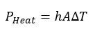
1] Conduction: This type of heat transfer occurs when two or more things are in contact. This could also be air. In PV modules, these occur due to the gradient between the modules and the things in contact such as the mount and the air. The thermal resistance and the configuration of the materials that are used to encapsulate PV cells into modules are what determine the ability of a module to transfer its heat to its surroundings. Conductive heat flow can somewhat be visualised using the mechanism of conductive current flow. Just like there is a driving force in a conductive current flow which is a difference in the voltage, there is a driving force in conductive heat flow which is a difference in temperature. Hence, temperature and heat (power) are related using the following equation which is similar to the equation that relates voltage to the current across a conductor:
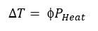
Here, PHeat is the heat or power generated by the module, f is the emitting surface’s thermal resistance in °C/W and ∆T is the change in temperature. The equation is valid on the assumption that the material of the module is uniform and in a steady state. The ‘f’ depends on the thickness of the material and its conductivity. Thermal resistance is given by:
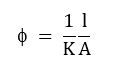
Here, A is the area of the surface that is conducting the heat, l is the length of the material through which there will be heat transfer and k is the thermal conductivity which is expressed in W/m °C. In order to determine the thermal resistance of a relatively more complex structure, the individual thermal resistances are added up in series or parallel. For instance, both the front and the rear surfaces of a module conduct heat to its environment. The two mechanisms are thought of as being operated in parallel with one another. Thus, the thermal resistance of the front and rear accumulate in parallel. On the other hand, the thermal resistances of the encapsulating material and the front glass would add in series.
2] Convection: When a material moves across the surface of another material, heat is transported away from the surface of the latter material and this is how convective heat transfer occurs. This happens with PV modules too as the wind blowing across a module transports the heat away. This transferred heat is given by:
Here, A is the area of contact between the two materials participating, h is the convection heat-transfer coefficient and its units are W/m2 °C, and is the difference in temperature of the two materials. The convection heat transfer coefficient (h) is determined experimentally for each system and its conditions. This is because it is quite complicate to compute.
3] Radiation: We know that any object will emit radiation depending upon its temperature. However, a PV module is not an ideal blackbody. For non-ideal blackbodies, the blackbody equation is modified and this is done by adding a new parameter called the emissivity, ε, of the material. The emissivity of a perfect blackbody is 1. The absorption properties tell a lot about the emissivity of an object since both will usually be very similar. Taking metals for instance, which usually have reduced absorption, have a lower emissivity as well. This is usually around 0.03. Now, to add the emissivity in the equation for emitted power density from a surface gives:
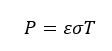
Here, is the emissivity, is the Stefan-Boltzmann constant, and T is the temperature of the cell in K. The net heat lost from the PV module because of radiation is the difference between the heat emitted from the surroundings to the PV module and the heat that the PV module emits to the surroundings. This is given by:
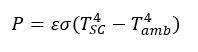
Here, TSC is the temperature of the solar cell and Tamb is the ambient temperature.
Nominal Operating Cell Temperature
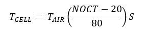
The ratings of a PV module are done in Standard Testing Conditions (STCs) i.e. at 1 kW/m2 and at 25°C. In reality, however, when they are operating in the field i.e. on the rooftop or in the ground, the temperature is usually higher and the insolation is usually somewhat lower than the STCs. So, to determine the power output of a cell or a module, it is essential to determine the operating temperature (expected) of the cell or module. The Nominal Operating Cell Temperature (NOCT) is the value of temperature reached by open-circuited solar cells in a module under certain conditions. These conditions include an Irradiance level of 800 W/ m2 on the cell surface, an air temperature of 20°C, the velocity of the wind as 1 m/s and the mounting to provide an open back side for the module(s). The following equation gives the cell temperature as a function of the air temperature, the NOCT and the insolation level in mW/cm2:
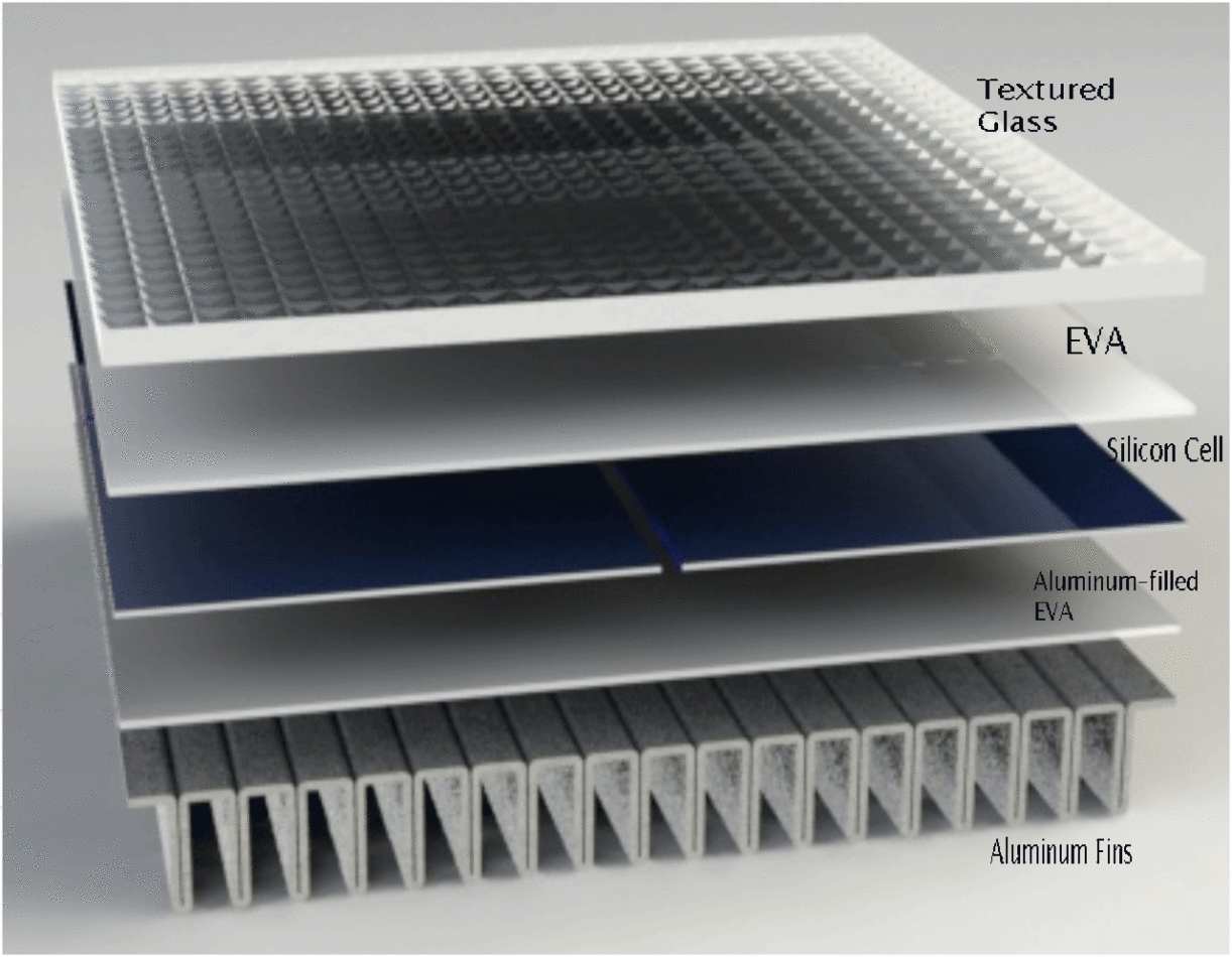
Heat loss through both, conduction and convection, are linearly related to the insolation that is incident on a PV cell/module. This is verified by the equations for solar radiation and temperature difference between the module and air. However, this is only true for a given wind speed, provided that there is not much considerable change in the thermal resistance and heat transfer coefficient with temperature. The NOCT is the best in the case where the module has fin-like structures made up of aluminium on its rear. These fins are used to cool the module down. This reduces the thermal resistance and increases the surface area for convectional heat loss. The figure below shows the layers of a PV module with fins made up of aluminium at the rear:
There are some other factors also that have an impact on the NOCT of a cell/module. For instance, the design of a module, especially the module materials and packing density of the cells, has a major effect on the NOCT. A lower packing density of the rear surface along with a lower thermal resistance could make a difference in temperature of 5°C or maybe even more. Mounting conditions of modules could also affect the operating temperature by affecting heat transfer. Both conductive and convective heat transfers are affected by the way in which the modules are mounted. If the rear surface is covered with no gap for air to flow (such as the case where the module is directly mounted on a roof) will have an infinite thermal resistance. Convectional transfer is also limited to only the front of the module. Thus, in roof-integrated mounting systems, the operating temperature is usually increased. This often causes the temperature of the modules to increase by 10°C.
Thermal Expansion and Thermal Stresses
Thermal expansion is the expansion of a material upon heating. It needs to be taken into account when making solar modules as cells can expand too. Consider the following animation:
The spaces between the cells try to increase by an amount δ which is given by:
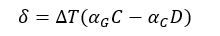
Here, αGC and αCD are the expansion coefficients of glass and the PV cell respectively, D is the width of the cell and C is the distance between two cells’ centres. As shown in the figure above, the connections between cells are looped. There are also double interconnects which are used to protect against the possibility of fatigue failure caused by that kind of stress. Additionally, all module interfaces are subject to temperature-related cyclic stress which may eventually lead to delamination of the module.
Conclusion
In this article, we have seen what the effect of temperature and heat is on photovoltaic cells and modules. We have looked at how heat is generated and lost in PV modules. We also looked at the Nominal Operating Cell Temperature of a PV module and how it is used as a more realistic parameter. We finally looked at thermal expansion and stresses and how they affect PV modules. The effect of different factors such as temperature and heat is an important area of study and research as it can help understanding those effects which would help in researching methods to tackle the negative effects.